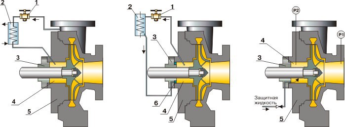
Р1 - pump suction pressure
Р2 - pressure in the oil seal chamber of the pump
Р2 > Р1, P2 > Рair
| API 682: Plan 21 | API 682: Plan 23 | API 682: Plan 32 |
| Schematic diagram of the system, which ensures efficiency of single seal with “protective” fluid, supplied from outside | Schematic diagram of the system, which ensures efficiency of single seal with fluid supply from the pump head into the seal chamber | Schematic diagram of the system, ensuring efficiency of single seal with impeller, which creates fluid circulation through the seal chamber in autonomous circuit |
| Pos. | Description |
| 1 | Control valve |
| 2 | Cooler (used when temperature of medium more then 150…200°С) |
| 3 | Mechanical seal UT type |
| 4 | Chamber of the pump |
| 5 | Pump |
| 6 | Impeller |
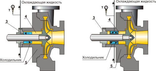
| Schematic diagram of the system, which ensures efficiency of seal with a built-in cooling unit and cooling fluid supply via sealing | Schematic diagram of the system, which ensures efficiency of single seal with a built-in cooling unit and cooling fluid supply via pump casing |
| Pos. | Description |
| 3 | Mechanical seal UT type |
| 4 | Chamber of the pump |
| 5 | Pump |
| Т | Output temperature measurement |
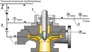
For condensate pumps, where dry operation of face seals is possible, guaranteed buffer fluid supply may be done according to the scheme below
Рbuffer = Рpump + (0,1…0,3) Mpa
Тbuffer <= 75 °С, Gbuffer >= 0,2 m3/hour
Fluid supply from the pump head and industrial pipe-line
| Поз. | Описание |
| 1 | Регулирующий вентиль |
| 2 | Торцовое уплотнение типа «УТД» |
| 3 | Дроссель |
| 4 | Обратный клапан |
| Р | Измерение давления |
| Т | Измерение температуры |
| G | Измерение расхода |
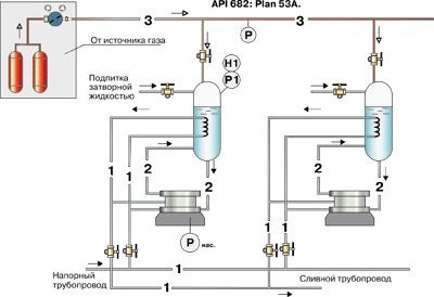
To maintain seals of a set of pumps, which operate similarly and are located closely to each other, it is possible to use the system, defined below.
Рbuffer = Рpump+(0,1…0,3) MPa
Р > Р1 – with gas supply
Р < Р1 – at gas depressurization
| Поз. | Описание |
| 1 | Трубопровод охлаждающей жидкости |
| 2 | Трубопровод затворной жидкости |
| 3 | Трубопровод газа (азот, воздух и пр.) |
| Р | Измерение давления |
| Н | Измерение уровня |
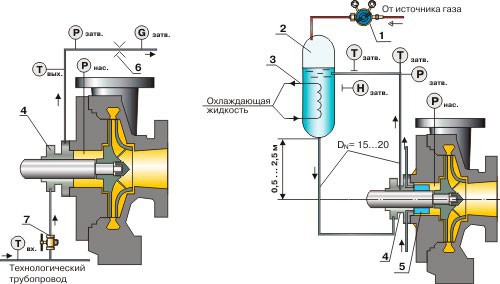
| API 682: Plan 54 | API 682: Plan 53A |
| It is not required to create overpressure in the SBTU reservoir after its filling. If pressure in pump seal chamber is less than design pressure of the reservoir (4MPa), it is not required to install a safety valve at reservoir pipes. Face seals of “Tandem” type may be used either with a cooling unit at temperatures of pump working medium up to 400 °С, or at temperatures of working medium up to 150 °С without it. Тcooling = 5...30 °С Gcooling = 0,2…1,5 m3/hour Schematic diagram of the system, which ensures efficiency of “Tandem” type seal with the SBTU reservoir |
The system functions at pressure of buffer fluid (pressure in the reservoir) constantly kept within the limits: Рbuffer = Рpump + (0,1…0,3) MPa Gcooling = 0,2…1,5 m3/hour If the temperature of pump working medium is 150°С, seals are used without a cooling unit, if the temperature of pumped medium is 150...400 °С - then a cooling unit is used. Schematic diagram of the system, which ensures efficiency of double seals with the SBTU reservoir |
При температурах рабочей среды насоса до 150°С применяются уплотнения без холодильника, при температурах перекачиваемой среды 150...400 °С - с холодильником.
| Поз. | Описание | Поз. | Описание |
| 1 | Редуктор газовый | 6 | Дроссель |
| 2 | Бачок под давлением | 7 | Регулирующий вентиль |
| 3 | Система охлаждения бачка | Р | Измерение давления |
| 4 | Торцовое уплотнение | Т | Измерение температуры |
| 5 | Холодильник уплотнения | Н | Измерение уровня |
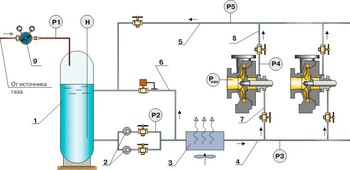
Р1 ~ Рpump;
Р3 > Р4 > Рpump;
Р4 > Р5 > Р1;
Rezerve pump start work if Р2 = Рpump + 0,2 MPa
Р1 ~ Рair;
Р4 << Рpump;
Р3 > Р4 > Р5;
Р3 ~ 0,6...1,0 MPa;
Р4 <= 0,1 MPa.
| Поз. | Описание | Поз. | Описание |
| 1 | Емкость с запасом затворной жидкости | 9 | Редуктор газовый |
| 2 | Основной и резервный насосы | Н | Измерение уровня |
| 3 | Теплообменник | Р1 | Давление в емкости |
| 4 | Напорный трубопровод | Р2 | Давление в напоре насосов |
| 5 | Сливной трубопровод | Р3 | Давление в напорном коллекторе |
| 6 | Байпасный трубопровод | Р4 | Давление в уплотнении |
| 7 | Трубопровод подвода затворной жидкости | Р5 | Давление в сливном коллекторе |
| 8 | Трубопровод отвода затворной жидкости | Рнас | Давление в сальниковой камере насоса |